
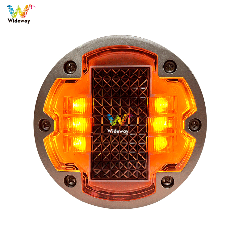
Installation of smart luminous pedestrian crossings in Shawan District, Leshan, Sichuan Province
I. Complete smart luminous crosswalk design proposal
Our company will develop smart illuminated crosswalk solutions and corresponding design drawings based on the intersection provided by the client. Once the design is complete, we will coordinate with the client to make necessary adjustments according to their requirements, and proceed with production only after all specifications have been verified as correct.
II. Construction Personnel
Our company will arrange for Engineer Li and our construction personnel to provide on-site installation guidance.
III. How to install cable conduits and connect floor tiles for smart luminous crosswalks
1. Floor tile installation:
1.1. Close off the access route and enclose Smart Illuminated Pavement Brick with fencing; ensure that the fencing is properly installed and that construction warning signs are clearly displayed to guarantee the safety of personnel working at the site.
1.2. Confirm the installation position, orientation, and spacing of the floor tile traffic lights.
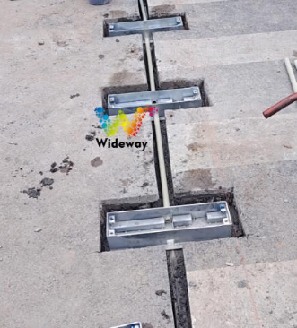
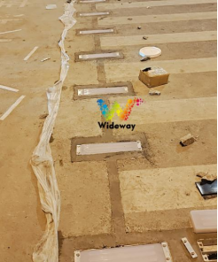
1.3. For the base of the patterned floor tiles, cut a straight slot. (See the figure below)
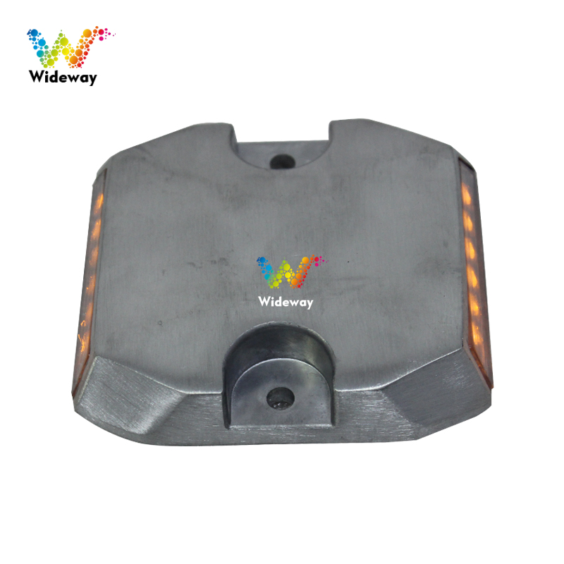
1.4. Slot Dimensions: The base dimensions of a single floor tile are 575 mm in length, 204 mm in width, and 110 mm in height. Therefore, the slot depth shall be 150 mm, and the slot width shall be 250 mm.
2. Installation of floor tiles on both sides of the zebra strip: the base dimensions of a single floor tile are 575 mm in length, 204 mm in width, and 110 mm in height. Accordingly, the slot dimensions shall be 600 mm in length, 150 mm in depth, and 250 mm in width. The slot dimensions are larger than those of the tile base to facilitate installation and ensure proper levelness.
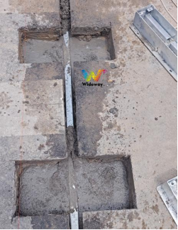
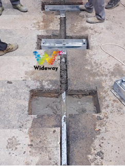
2.1. Cutting the cable routing groove: Cable routing involves selecting the optimal position for routing from the junction box to the steel channel, then cutting a routing groove for the PPR heat-fused circular conduit; the depth from the top of the PPR circular conduit to the ground shall be approximately 10 cm.
The incision width shall be 5 cm (determined based on the actual number of power cables in each direction at the junction).
Primary function: The main low-voltage power line (DC24V) from the controller’s output port must be seamlessly connected to the center of each floor tile, with no additional interfaces permitted.

2.2 Clear away debris: Remove all the construction waste that was cut out earlier, then level the surface below to facilitate placement into the steel trough and the illuminated smart crosswalk paving tiles. Finally, transport and dispose of all generated waste.
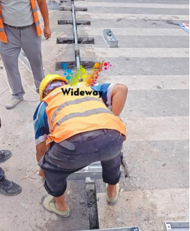
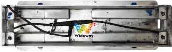
2.3 Installation of the base: Place the base into the pre-dug slot, then secure Smart Illuminated Pavement Brick to the square channel using screws and nuts. Position the product along this reference leveling line, then adjust Smart Illuminated Pavement Brick to achieve proper levelness. Place the smart crosswalk paving tiles, then locate the corresponding output ports along these tiles. Each base of the smart crosswalk has an output port in each direction; align these output ports with the corresponding input ports.
2.12 Concrete Pouring: After completing all inspections and confirming that everything is in order, proceed with surface treatment and protective coating of the illuminated zebra crossing. When pouring concrete [the concrete must meet high standards, with a grade of C40 or higher], ensure that each illuminated paving tile is tightly compacted on both sides, and [use a vibratory rod for compaction]. During backfilling, the sub-base layer may be laid in half; however, a thorough inspection must be conducted to ensure no issues exist before proceeding with the pavement pouring.
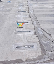
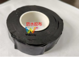
2.4 Prepare installation materials: Prepare wiring of appropriate spacing for the floor tiles, with the wires extending from both lateral ends of the base; prepare connection joints; prepare structural adhesive, waterproof tape, PPR pipes (32*3.6*1.6 MPa), etc. Use 3×1.5 mm² main cables for the main cable runs.
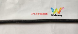
2.5 Wiring: The floor tiles shall be wired in parallel. A main power supply line (DC24V, hereinafter referred to as the “main line”) shall be extended from the floor tile control box to each floor tile lamp socket, where Smart Illuminated Pavement Brick shall be connected to the corresponding floor tile luminaire. To connect, first secure the connector, then insert Smart Illuminated Pavement Brick into a T-junction connector, and finally tighten Smart Illuminated Pavement Brick (Note: Ensure that the pin holes are precisely aligned before insertion). After the connection is complete, secure the connector using a zip tie. The three-core wires on the floor tile luminaire consist of: a blue wire serving as the common negative terminal; a brown wire serving as the red light positive terminal; and a yellow wire serving as the green light positive terminal. Once the wiring is complete, perform a circuit test; all floor tiles shall exhibit consistent lighting behavior—either all red lights or all green lights. Connect the main line to the DC24V terminal of the equipment in the control box, and then connect the pedestrian lighting signal wire of the traffic signal controller to the corresponding terminal of the control box. (Triple waterproof rating, IP68 / ROHS compliant; waterproof base and fully filled floor tiles)
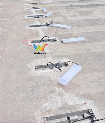
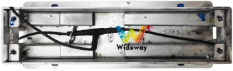
2.6 Power-on Test: Connect each completed power cable pair to the output ports of the control box (Note: Do not apply 220 V, as the Smart Zebra Crossing is designed for 24 V DC power supply; applying 220 V to the Smart Zebra Crossing lights will directly burn out all devices).
Important Note: Please note that this is a low-voltage test; only a 24 V power supply may be used to test this product. Connect the positive and negative terminals of the power supply to the product as follows: red terminal to red terminal, green terminal to green terminal, and common negative terminal to common negative terminal. Once all connections are verified, turn on the power supply of the control box.
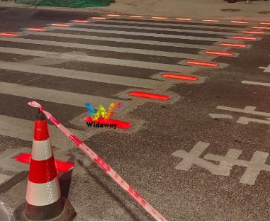
2.7 Connecting power cords via extension cords: After powering on the smart zebra-crossing illuminated floor tiles and confirming that all systems are functioning correctly, connect each power cord to its corresponding extension cord. When using the extension cords, measure the distance and connect them directly to the control host unit (important note: the extension cord section must be fully wrapped with waterproof electrical tape; Smart Illuminated Pavement Brick
must not remain exposed). At the connection point, disconnect all wires, then cross-connect the power cords, and tighten the connections. After tightening, each individual wire must be secured separately using waterproof electrical tape, with at least 10 full wraps applied—each wrap must be tightly and evenly pressed against the surface. Under no circumstances should the entire tape surface appear loose after completing the 10 wraps. (Note: To prevent subsequent malfunctions, when connecting the wires, ensure that each wire is connected at a distinct position; do not connect three wires at the same location.)
2.8. Gluing at the connection points of luminous floor tiles: After the smart crosswalk has been powered on and verified to be functioning correctly, fix the connection points into the dedicated slots of the smart crosswalk. Then, apply the specialized S2118-A/B adhesive in reverse orientation until fully filled; use an adhesive ratio of 10:1. Ensure that the adhesive and wire ends are thoroughly sealed and well-integrated to achieve optimal waterproof performance. Fill the adhesive completely into the centrally positioned slots. (Note: The adhesive must be thoroughly mixed before use.)
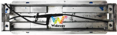
2.9 Place the vibration damping rubber pad: When the adhesive is nearly dry, cover the assembly with a 5 mm thick specialized anti-slip vibration damping rubber pad, positioning the pad beneath the steel plate.
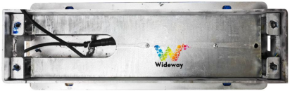
2.10 Install the floor tiles: Next, place the floor tiles into the base, then secure them using two cover strips and four screws.
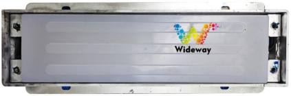
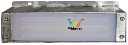
2.11 Surface treatment of luminous paving tiles: To ensure that the luminous surface of the smart crosswalk remains free from concrete contamination, the entire luminous surface must be fully covered with red-and-yellow adhesive tape prior to concrete pouring, thereby preventing the surface from becoming contaminated during the concrete placement process.
IV. Smart Illuminated Pavement Brick Power-On Test
Once all floor tiles have been installed, restore power and perform a test to check for short circuits or any lights failing to illuminate; connect each powered cable set to the output ports of the control box (Note: Under no circumstances should 220 V be applied, as the Smart Zebra Crossing is designed for 24 V DC power supply; applying 220 V to the Smart Zebra Crossing lights will directly destroy all devices).
Important Note: Please note that this is a low-voltage test; only a 24 V power supply may be used to test this product. Connect the positive and negative terminals of the power supply to the product as follows: red terminal to red terminal, green terminal to green terminal, and common negative terminal to common negative terminal. Once all connections are verified, turn on the power supply of the control box.
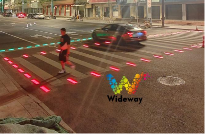
V. Final Completion
Clear the work area, securely close the control box door, and conduct another inspection of all equipment, the road surface, and the smart zebra crossing.
